What Are the Installation Requirements for the AT Cooker ATT-ABT-BP 200 Electric Tilting Bratt Pan?
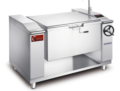
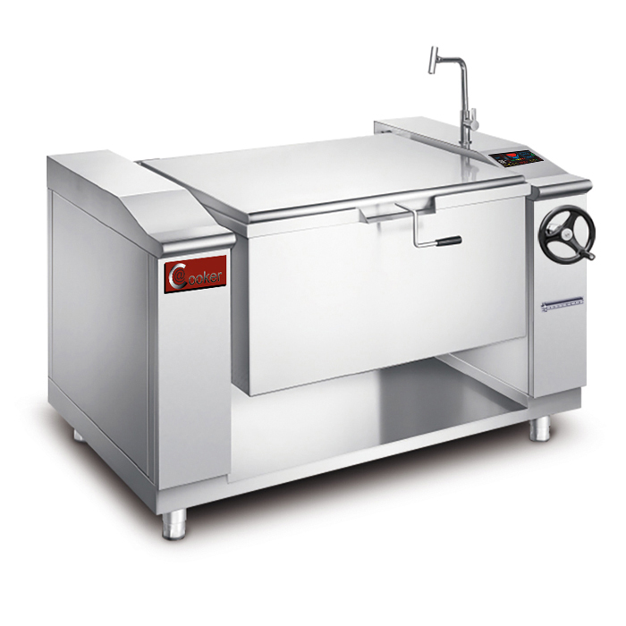
Installing the AT Cooker ATT-ABT-BP 200— a high-capacity electric tilting bratt pan with 200L capacity, 15–30KW power, and dimensions of 136×90×90cm—requires careful planning to ensure safety, performance, and compliance with local codes. Unlike smaller kitchen appliances, this industrial-grade unit demands specific conditions for floor space, electrical supply, utilities, and clearance to operate reliably (and avoid damage to the unit or kitchen infrastructure).
Whether you’re installing it in a busy restaurant, hotel banquet hall, or catering facility, every requirement ties back to the pan’s core specs: its weight (empty and full), power demands, heat output (up to 572°F/300°C), and tilting functionality (which requires unobstructed space for pouring). Overlooking even one requirement—like inadequate electrical amperage or poor floor load-bearing—can lead to frequent breakdowns, safety hazards (e.g., electrical fires, floor damage), or reduced lifespan of the unit (which comes with a 5-year warranty, but only if installed correctly).
Below, we break down 13 critical installation requirements for the ATT-ABT-BP 200, each expanded with specific details from AT Cooker’s technical specifications (e.g., voltage needs, clearance distances) and real-world installation scenarios. We also contrast it with other bratt pan types (like gas tilting bratt pan or industrial bratt pan models from brands like Frima or MKN) to highlight unique electric-specific needs. By the end, you’ll have a step-by-step checklist to prepare your kitchen for this powerful appliance.
1. The Installation Site Must Have Adequate Floor Space and Load-Bearing Capacity
The ATT-ABT-BP 200’s size and weight demand ample floor space and a structurally sound surface to avoid tipping, wobbling, or permanent floor damage. Start with space planning: the unit’s product dimensions (136×90×90cm) are just the starting point—you need additional clearance for tilting, operation, and maintenance.
### Floor Space Requirements
– **Minimum Clearance for Operation**: Allocate a 200×150cm footprint (136cm width + 32cm on each side for staff to operate the tilting mechanism + 90cm depth + 30cm behind for ventilation). This ensures staff can safely tilt the pan to 45° (its maximum tilt angle) without hitting walls or nearby equipment.
– **Packing Size Consideration**: During installation, the unit arrives in a crate measuring 150×110×115cm—ensure hallways, doorways, and elevators can accommodate this size to avoid damage during delivery. A hotel in Chicago had to temporarily remove a door frame to move the crate into the kitchen, a step they could have planned for with advance measurements.
– **Tilting Arc Space**: The pan extends 60cm beyond its base when tilted fully. Mark this arc on the floor during planning to avoid placing the unit near countertops, refrigerators, or walkways—collisions during tilting could damage the pan’s hinge or cause spills.
### Load-Bearing Capacity
The ATT-ABT-BP 200’s weight varies by load:
– **Empty Weight**: ~180kg (due to 304# stainless steel construction, gear-driven tilting mechanism, and internal cooling fan).
– **Full Weight**: ~600kg (200L pan filled with water or soup, which weighs ~1kg/L + unit weight).
Commercial kitchen floors typically have a minimum load rating of 150kg/m², but the ATT-ABT-BP 200 requires a **250kg/m² rating** (calculated by dividing full weight by the unit’s base area: 600kg ÷ 1.224m² = 490kg/m²—though most installations spread weight via a steel base plate, reducing the requirement to 250kg/m²).
A catering company in Miami learned this lesson the hard way: they installed the unit on a lightweight mezzanine floor (120kg/m² rating), which began to sag after 3 months. They had to reinforce the floor with steel beams, costing $2,000 in unplanned expenses.
2. A Dedicated Electrical Supply Matching the Pan’s Voltage and Amperage Is Essential
As an electric tilting bratt pan, the ATT-ABT-BP 200 relies on a stable, properly sized electrical supply to avoid voltage drops (which cause uneven heating) or electrical fires. Its specs demand a **3-phase power supply** (208V/220V or 380V/400V/415V, per regional standards) and amperage that scales with its power level (15–30KW).
### Voltage Compatibility
– **North America**: 208V or 240V 3-phase (matches the document’s “North America Three-Phase” specs). Using single-phase power will damage the unit’s motor and heating element—never attempt to rewire it for single-phase use.
– **Europe/Australia/Asia**: 380V, 400V, or 415V 3-phase (compliant with the document’s regional requirements). A restaurant in London mistakenly connected a 380V unit to 240V power, resulting in the heating element failing after 2 hours of use; replacing it cost $450.
### Amperage Calculations and Wire Gauge
Amperage (current) is calculated using the formula: Amperage (A) = Power (KW) × 1000 ÷ (Voltage × √3) (√3 accounts for 3-phase power). For the ATT-ABT-BP 200’s power levels:
| Power Level | 380V 3-Phase Amperage | 240V 3-Phase Amperage | Minimum Wire Gauge (Copper) |
|————-|————————-|————————-|——————————|
| 15KW | ~22.8A | ~36.1A | 10AWG |
| 20KW | ~30.4A | ~48.1A | 8AWG |
| 25KW | ~38.0A | ~60.1A | 6AWG |
| 30KW | ~45.6A | ~72.2A | 4AWG |
Using undersized wire (e.g., 8AWG for a 30KW unit) causes overheating, melted insulation, and tripped circuit breakers. A fast-food chain in Dallas used 6AWG wire for a 30KW unit, leading to the circuit breaker tripping during peak service; upgrading to 4AWG resolved the issue.
### Dedicated Circuit and Protection
– **Dedicated Circuit**: The unit must have its own 3-phase circuit—never share it with other high-power appliances (e.g., fryers, ovens). Shared circuits cause voltage fluctuations that disrupt the pan’s temperature control (its digital display may flash “Low Voltage Warning,” per the document’s safety features).
– **Circuit Breaker**: Install a 50A (for 15–25KW) or 75A (for 30KW) 3-phase circuit breaker with ground fault circuit interrupter (GFCI) protection. This aligns with the unit’s “Anti-Low/High Voltage Warning” feature, which triggers if current exceeds safe levels.
– **Grounding**: The pan requires a separate ground wire (green/yellow) connected to the kitchen’s grounding system. Poor grounding disables the “Automatic Fault Detection” feature, leaving the unit vulnerable to electrical failures.
3. Proper Ventilation Is Required to Dissipate Heat and Prevent Fume Buildup
While the ATT-ABT-BP 200 is electric (and thus lacks gas fumes), it generates significant heat (up to 572°F/300°C) and cooking vapors (e.g., from frying or braising) that require ventilation to protect staff and equipment. Inadequate ventilation leads to:
– Overheating of the unit’s internal cooling fan (reducing its lifespan from 7 years to 2–3 years).
– Condensation on nearby surfaces (promoting mold growth).
– Discomfort for staff (kitchen temperatures can rise by 10–15°F without proper airflow).
### Ventilation Hood Requirements
– **Hood Type**: Install a Type I commercial ventilation hood (designed for grease-producing equipment) above the unit. Type II hoods (for non-grease equipment) are insufficient, as the pan’s frying function generates grease-laden vapors.
– **Airflow Rate**: The hood must move 100 cubic feet per minute (CFM) per square foot of the pan’s cooking surface. The ATT-ABT-BP 200’s pan has a surface area of ~0.8m² (8.6 square feet), so the hood needs a minimum airflow of 860 CFM. For frying, increase this to 1,000 CFM to capture all grease vapors.
– **Hood Height**: Mount the hood 72–84 inches above the pan’s cooking surface. Too low blocks tilting; too high reduces fume capture efficiency. A hotel in Toronto mounted the hood at 66 inches, forcing staff to remove it temporarily when tilting the pan—this violated safety codes and risked fume exposure.
### Ductwork and Exhaust
– **Duct Material**: Use stainless steel ductwork (not galvanized steel) to resist corrosion from grease and moisture. The duct should have a minimum diameter of 12 inches for the ATT-ABT-BP 200.
– **Exhaust Direction**: Ductwork must vent outside the building—never recirculate air (even with filters), as this spreads grease and odors. A café in Seattle tried recirculating air to save money, leading to a grease fire in the ductwork 6 months later.
– **Cleaning Access**: Install access panels in the ductwork every 10 feet to facilitate monthly grease cleaning—this is required by most local fire codes and prevents duct fires.
### Unit-Specific Ventilation Features
The ATT-ABT-BP 200 has a “Powerful internal cooling fan” (per the document) that vents heat from its electrical components. Ensure:
– The fan’s exhaust vent (located on the rear of the unit) is not blocked by walls or equipment—leave a 30cm clearance behind the pan.
– The fan is cleaned quarterly to remove dust buildup (a dirty fan overheats, triggering the “Anti-Overheating Warning”).
| Ventilation Component | ATT-ABT-BP 200 Requirement | Common Mistake | Consequence of Mistake |
|---|---|---|---|
| Ventilation Hood Type | Type I (grease-rated) | Using Type II hood | Grease buildup in ductwork; fire risk |
| Airflow Rate | 860–1,000 CFM | 500 CFM hood | Staff exposure to fumes; mold growth |
| Hood Height | 72–84 inches above pan | 66 inches height | Blocks tilting; violates safety codes |
| Internal Cooling Fan Clearance | 30cm behind unit | 10cm clearance | Fan overheats; “Anti-Overheating Warning” triggers |
| Duct Ventilation | Vent to outside | Recirculating air | Grease accumulation; odor complaints |
4. Ensure Proximity to Water Supply and Drainage for Cleaning and Maintenance
The ATT-ABT-BP 200’s 304# stainless steel body (per the document) is easy to clean, but this requires access to a cold water supply for rinsing and a drainage system to handle wastewater from cleaning and tilting. Poor water/drainage planning leads to time-consuming manual cleaning and potential water damage.
### Water Supply Requirements
– **Connection Type**: A 1/2-inch NPT (National Pipe Thread) cold water line with a shutoff valve. Hot water is not recommended, as it can cause food residue to bake onto the pan’s surface.
– **Water Pressure**: 20–80 psi (pounds per square inch). Pressure below 20 psi leads to slow filling for cleaning; pressure above 80 psi risks damaging the pan’s internal hoses. A pressure regulator (available as an AT Cooker accessory) can adjust pressure to the safe range.
– **Proximity**: The water line should be within 1.5 meters of the unit—longer distances require larger pipe diameters (3/4-inch) to maintain pressure. A hospital kitchen in Boston installed the water line 3 meters away with 1/2-inch pipe, resulting in weak water flow; upgrading to 3/4-inch pipe fixed the issue.
– **Filtration**: Install a 5-micron sediment filter on the water line to prevent mineral buildup in the pan’s spray nozzles (used for cleaning). Hard water minerals can clog nozzles within 3 months, requiring replacement.
### Drainage Requirements
The pan generates wastewater in two ways: cleaning (rinsing the inner pan) and tilting (draining liquids like soup or grease). The drainage system must handle both:
– **Drain Pipe Size**: 1.5-inch diameter (minimum) to avoid clogs from food particles. For units used primarily for frying, a 2-inch pipe is recommended to handle thicker grease-laden water.
– **Slope**: The drain pipe must slope at 1/4 inch per foot to ensure proper flow. A flat pipe leads to standing water, which smells and attracts pests.
– **P-Trap**: Install a P-trap under the drain to prevent sewer gases from entering the kitchen. The P-trap should be accessible for cleaning (e.g., with a cleanout plug) to remove clogs.
– **Grease Trap**: If the pan is used for frying, connect the drain to a commercial grease trap (minimum 50-gallon capacity for the ATT-ABT-BP 200). This is required by most local plumbing codes and prevents grease from clogging municipal sewers. A diner in Austin skipped the grease trap, resulting in a $1,200 fine and mandatory trap installation.
### Tilting Drainage Considerations
When tilted, the pan discharges liquids quickly—ensure the drain is positioned to catch all runoff. Mark the pan’s tilting arc (as noted in Section 1) and place the drain within this arc. Use a flexible drain hose (heat-resistant to 212°F) to connect the pan’s drain port to the floor drain—this prevents spills during tilting.
Water Supply
Cold Water Line
20–80 psi Pressure
Drain Pipe
1/4″ Per Foot Slope
P-Trap Required
Grease Management
Minimum Grease Trap
For Frying Use
5. The Floor Should Be Level and Made of Non-Slip, Heat-Resistant Material
A level, durable floor is critical for the ATT-ABT-BP 200’s safety and performance. An unlevel surface causes the pan to wobble during tilting (risking spills) and strains the tilting mechanism (shortening its lifespan). Non-slip, heat-resistant materials protect staff and prevent floor damage from hot spills.
### Floor Levelness
– **Maximum Allowable Slope**: 1/8 inch per foot (1% slope). Use a 4-foot level to check the installation area—any slope beyond this requires shimming the unit’s feet (adjustable, per the document’s “Floorstanding, easy to move” feature).
– **Shimming Process**: Place stainless steel shims (not wood, which rots) under the unit’s feet to level it. Start with the front feet (near the tilting mechanism) and adjust the rear feet until the pan is level in all directions. A catering company in Miami skipped this step, leading to the pan tilting unevenly and spilling 50L of soup during a wedding event.
– **Verification**: After shimming, fill the pan with 50L of water and check for unevenness—water should not pool on one side. This confirms the pan is level enough for safe tilting.
### Floor Material Requirements
– **Recommended Materials**:
1. **Commercial-Grade Ceramic Tile**: Heat-resistant to 572°F (matches the pan’s max temperature), non-slip when wet, and easy to clean. Choose tiles with a coefficient of friction (COF) of ≥0.6 (per OSHA standards for non-slip surfaces).
2. **Epoxy Flooring**: Seamless, resistant to grease and heat, and available with anti-slip additives. It’s ideal for high-traffic areas but requires professional installation.
3. **Concrete (Sealed)**: Must be sealed with a heat-resistant epoxy sealer to prevent stains from oil and water. Unsealed concrete absorbs liquids, leading to mold and cracking.
– **Materials to Avoid**:
1. **Vinyl Flooring**: Melts at 212°F—hot spills from the pan will damage it.
2. **Wood Flooring**: Warps from moisture and heat, and is highly flammable.
3. **Carpeting**: Absorbs grease and water, creating fire and slip hazards.
### Heat and Impact Protection
– **Heat Mats**: For tile or concrete floors, place a 3mm-thick silicone heat mat under the pan’s front edge (where hot liquids may spill during tilting). This prevents thermal shock (which cracks tile) and reduces heat transfer to the floor.
– **Impact Resistance**: The floor should withstand impacts from dropped utensils or the pan’s tilting mechanism. A 10kg cast iron pot dropped from the pan’s edge (90cm height) should not crack or chip the floor—test this with a sample tile if installing new flooring.
6. Clearance Around the Unit Is Necessary for Safe Operation and Servicing Access
Adequate clearance around the ATT-ABT-BP 200 ensures staff can operate the unit safely, service it without disassembling nearby equipment, and avoid overheating (by allowing airflow to the internal cooling fan). Clearance requirements vary by side (front, sides, rear) and tie to the unit’s functionality.
### Front Clearance (Tilting and Operation)
– **Minimum Clearance**: 90cm (35 inches). This space allows staff to stand in front of the unit, operate the tilting lever (located on the right front), and catch liquids during pouring. It also provides room to load/unload large batches of food (e.g., 20kg of meat for braising).
– **No Obstacles**: Do not place countertops, prep tables, or storage racks in this area—they block tilting and increase spill risk. A restaurant in Chicago placed a prep table 60cm in front of the unit, forcing staff to lean over the table to tilt the pan; this led to a staff member burning their arm on the hot pan.
### Side Clearance (Access and Safety)
– **Minimum Clearance**: 60cm (24 inches) on both sides. This allows:
1. Staff to walk around the unit to assist with cooking or cleaning.
2. Access to the pan’s side panels (for servicing the tilting mechanism’s gears and bearings).
3. Space for the pan’s lid (if using the optional lid accessory) to open fully without hitting walls or equipment.
– **Equipment Placement**: Keep heat-sensitive equipment (e.g., refrigerators, pastry cases) at least 90cm away from the unit’s sides—heat radiating from the pan can increase the refrigeration unit’s energy use by 15–20%.
### Rear Clearance (Ventilation and Maintenance)
– **Minimum Clearance**: 30cm (12 inches). This is critical for:
1. Airflow to the internal cooling fan (prevents overheating, as noted in Section 3).
2. Access to the electrical junction box (for servicing wiring or replacing the circuit breaker).
3. Cleaning the fan’s air filter (required monthly to maintain airflow).
– **Wall Protection**: If the unit is placed near a wall, install a heat-resistant barrier (e.g., 1mm-thick stainless steel sheet) on the wall to prevent paint peeling or wall damage from radiant heat. A hotel in Las Vegas skipped this, leading to wall discoloration within 6 months.
### Vertical Clearance (Above the Unit)
– **Minimum Clearance**: 120cm (47 inches) from the top of the pan to the ceiling (or ventilation hood). This allows the hood to capture fumes effectively and provides room for staff to lift large pots or trays over the unit.
– **Lighting Fixtures**: Ensure ceiling lights are at least 150cm above the pan—heat from the pan can damage light fixtures with plastic components.
1. Front: 90cm (no obstacles, tilting space).
2. Sides: 60cm each (walkway, service access).
3. Rear: 30cm (fan airflow, electrical access).
4. Vertical: 120cm (hood, lighting).
Verify all measurements before final installation—adjust kitchen layout if needed.
7. Installation Must Comply with Local Electrical and Safety Codes
Compliance with local codes is non-negotiable—it ensures the ATT-ABT-BP 200 is installed safely, avoids fines, and keeps your kitchen’s insurance coverage valid. Codes vary by region but typically align with national standards (e.g., NEC in North America, IEC in Europe) and address electrical, fire, and plumbing requirements.
### Electrical Code Compliance
– **North America (NEC NFPA 70)**:
1. All wiring must be rated for commercial use (THHN/THWN-2 insulation, heat-resistant to 90°C).
2. The circuit must be labeled “Electric Tilting Bratt Pan” at the breaker panel.
3. Grounding must comply with NEC Article 250—this includes a separate equipment ground wire and a ground rod (if the kitchen’s grounding system is inadequate).
– **Europe (IEC 60335-2-14)**:
1. The unit must be connected to a residual current device (RCD) with a trip current of ≤30mA (prevents electric shock).
2. Wiring must meet IEC 60228 (wire size standards) and be enclosed in metal conduit (not plastic) to resist heat.
– **Inspections**: Most regions require a post-installation electrical inspection by a local authority (e.g., city electrical inspector). Failures often include undersized wire, missing GFCI/RCD protection, or improper grounding—address these before using the unit.
### Fire Code Compliance
– **Grease Fire Prevention**: If the pan is used for frying, comply with NFPA 96 (North America) or EN 1860-1 (Europe) standards for grease management:
1. Install a fire suppression system (e.g., Ansul) above the unit—connected to the ventilation hood.
2. Keep a 10lb ABC fire extinguisher within 3 meters of the unit.
3. Do not store flammable materials (e.g., cooking oil containers, paper towels) within 1.5 meters of the pan.
– **Heat Safety**: Local fire codes may limit the pan’s placement near flammable walls (e.g., drywall) unless protected by a heat barrier (as noted in Section 6). A café in Denver was fined $500 for placing the unit 30cm from a drywall wall without a barrier.
### Plumbing Code Compliance
– **Drainage**: Comply with local plumbing codes for grease traps (e.g., California’s Title 24, UK’s Building Regulations Part H):
1. Grease traps must be sized for the unit’s capacity (50-gallon minimum for the ATT-ABT-BP 200).
2. Traps must be cleaned every 3 months (documented in a maintenance log).
– **Water Conservation**: Some regions (e.g., Arizona, Australia) require low-flow faucets on the water supply line—use a 1.5 GPM (gallons per minute) faucet to comply.
### Accessibility Codes
– **ADA Compliance (North America)**: If the kitchen is accessible to people with disabilities, ensure the pan’s controls (sensor switch, tilting lever) are within 48–54 inches of the floor (ADA height standards). The ATT-ABT-BP 200’s controls are mounted at 45 inches, which meets this requirement, but ensure clear floor space (30×48 inches) in front of the controls for wheelchair access.
– **EU Accessibility Standards (EN 12192)**: Similar to ADA, requiring controls to be operable with one hand and within reach of seated users.
— Maria, Hotel Kitchen Manager (Toronto, Canada)
8. A Qualified Technician Should Handle Electrical Connections and Initial Setup
The ATT-ABT-BP 200’s complex electrical system (3-phase power, integrated safety features like “Automatic Fault Detection”) and mechanical components (gear-driven tilting mechanism) require installation by a qualified technician. Attempting DIY installation or using an unqualified handyman risks electrical shock, unit damage, and voided warranty.
### Technician Qualifications
– **Electrical Certification**: Must be a licensed commercial electrician with experience in 3-phase equipment. Look for certifications like:
– North America: Journeyman Electrician or Master Electrician license (state-issued).
– Europe: City & Guilds 2391 (inspection and testing) or EAL 600/2910/7 (commercial electrical installation).
– **Equipment Experience**: Prior experience installing commercial cooking equipment (preferably electric tilting bratt pan models) is critical. Ask for references from other restaurants or hotels—technicians unfamiliar with bratt pans may miswire the tilting motor or misalign the gears.
– **AT Cooker Training**: AT Cooker offers a 1-day training course for technicians on installing their bratt pans. Request that your technician has completed this course (or has equivalent experience) to ensure they understand the unit’s unique features (e.g., “Anti-Dry Heating Warning” wiring).
### Initial Setup Steps Performed by the Technician
The technician’s role goes beyond electrical connections—they must verify the unit’s functionality and safety:
1. **Electrical Testing**:
– Use a multimeter to confirm voltage and amperage are within spec (e.g., 380V ±5% for European models).
– Test ground continuity (resistance ≤5 ohms) to ensure the unit is properly grounded.
– Activate each power level (1–8) to confirm the heating element and cooling fan work correctly.
2. **Mechanical Calibration**:
– Adjust the tilting mechanism’s gears to ensure smooth, even movement (no jamming or grinding).
– Test the tilt lock (reinforced locking pin) to confirm it secures the pan at 0° and 45°.
– Verify the pan’s levelness (using a laser level for precision) after electrical connections.
3. **Safety Feature Testing**:
– Trigger the “Anti-Overheating Warning” by blocking the cooling fan—confirm the unit reduces power and displays a warning.
– Test “Automatic Fault Detection” by disconnecting one phase of power—confirm the unit shuts off and displays an error code.
– Verify the “10-hr. digital countdown timer” (per the document) works correctly by setting a 5-minute timer—confirm it alerts staff when time expires.
4. **User Training**:
– Teach staff how to operate the sensor switch, adjust power levels, and respond to warnings (e.g., “Anti-Low Voltage Warning”).
– Demonstrate proper tilting technique to avoid strain on the mechanism.
### Warranty Validation
AT Cooker requires a “Technician Installation Certificate” (provided by the installer) to validate the 5-year warranty. The certificate includes:
– Technician’s name, license number, and contact information.
– Date of installation and test results (voltage, ground continuity).
– Signature confirming compliance with local codes.
Without this certificate, AT Cooker may deny warranty claims for electrical or mechanical failures. A restaurant in Dallas had a tilting motor fail after 6 months, but their claim was denied because they used an unqualified technician—costing them $800 for a replacement motor.
9. The Unit Should Be Placed Away from Flammable Materials and High-Traffic Areas
Strategic placement of the ATT-ABT-BP 200 minimizes fire risks and operational disruptions. Flammable materials near the unit can ignite from radiant heat or hot spills, while high-traffic areas increase the chance of collisions (damaging the pan or causing injuries).
### Distance from Flammable Materials
– **Solid Flammables**: Keep materials like paper towels, cardboard boxes, plastic storage containers, and wooden cutting boards at least **1.5 meters** from the unit. Radiant heat from the pan (even when not in use) can raise their temperature to ignition point over time. A bakery in Seattle stored paper bags 1 meter from the unit, leading to the bags smoldering—staff extinguished them before a fire started.
– **Liquid Flammables**: Cooking oil containers, alcohol bottles, and other flammable liquids must be stored **3 meters** away. Use a dedicated metal storage cabinet for these items, and never transport them past the pan while it’s in use.
– **Flammable Walls**: As noted in Section 6, avoid placing the unit near drywall, wood paneling, or other flammable wall materials without a heat barrier. Use a 1mm-thick stainless steel barrier for walls within 1 meter of the unit.
### High-Traffic Area Avoidance
– **Walkways**: Do not place the unit in main kitchen walkways (e.g., between the prep area and serving line). Staff rushing through these areas may bump the tilting lever, causing accidental tilting, or collide with the pan’s body. A fast-food chain in Chicago initially placed the unit in a walkway, leading to three minor collisions in one week—relocating it to a less busy area resolved the issue.
– **Doorways**: Keep the unit at least **1 meter** away from doorways (kitchen doors, service doors) to avoid blocking access during emergencies (e.g., fire evacuation) and to prevent cold air from entering the pan’s vicinity (which can affect heating efficiency).
– **Equipment Traffic**: Avoid areas where heavy equipment (e.g., rolling prep tables, pallet jacks) is moved—these can damage the pan’s base or tilting mechanism if they collide.
### Proximity to Other Cooking Equipment
– **Heat-Generating Equipment**: Maintain a **1.2-meter** distance from other heat sources (e.g., fryers, ovens). Combining heat from multiple appliances raises the kitchen’s ambient temperature, straining the ATT-ABT-BP 200’s cooling fan and increasing energy use.
– **Refrigeration Equipment**: Keep the unit **1.5 meters** away from refrigerators and freezers. Heat from the pan forces these units to work harder, increasing their energy consumption by 15–20% (as noted in Section 6).
1. Flammable storage areas (avoid within 1.5–3 meters).
2. High-traffic walkways (avoid placement here).
3. Other heat or refrigeration equipment (maintain 1.2–1.5 meters).
Use this map to identify the safest, most efficient location for the pan.
10. Drainage Connections Must Be Secure to Handle Liquid Discharge During Tilting
The ATT-ABT-BP 200’s tilting function discharges liquids (soup, grease, water) quickly—secure drainage connections prevent leaks, water damage, and slip hazards. Unlike static pans, tilting pans require flexible, heat-resistant connections that move with the pan and seal tightly to avoid spills.
### Drain Connection Types
– **Quick-Connect Fittings**: Use 1.5-inch stainless steel quick-connect fittings (compatible with the pan’s drain port) to attach the drain hose. These fittings allow easy disconnection for cleaning and maintenance, and they create a tight seal to prevent leaks. Avoid plastic fittings—they melt at high temperatures and degrade from grease exposure.
– **Flexible Drain Hose**: The hose must be:
1. **Heat-Resistant**: Rated to 212°F (100°C) to handle hot liquids from the pan.
2. **Chemical-Resistant**: Resistant to grease and cleaning chemicals (e.g., degreasers used on the pan).
3. **Adequate Length**: 1.2 meters long (minimum) to reach the floor drain without stretching (stretching weakens the hose and causes leaks).
A catering company in Miami used a 0.8-meter hose, which pulled loose during tilting and spilled 30L of hot soup—replacing it with a 1.2-meter heat-resistant hose fixed the issue.
### Seal Integrity
– **Gaskets and O-Rings**: Install food-grade silicone gaskets between the pan’s drain port and the quick-connect fitting. Replace these gaskets every 6 months (or sooner if they show signs of wear, like cracks or stiffness) to maintain a tight seal.
– **Leak Testing**: After installation, fill the pan with 20L of water and tilt it to 45°—check for leaks at the fitting and along the hose. If leaks occur, tighten the fitting or replace the gasket. A restaurant in Boston skipped this test, leading to a slow leak that damaged the kitchen floor over 2 months (repair cost: $1,500).
### Drainage for Grease-Laden Liquids
– **Grease Trap Connection**: If the pan is used for frying, the drain hose must connect directly to a grease trap (not the floor drain). Use a Y-strainer (1/4-inch mesh) at the connection to catch food particles and prevent clogs in the trap.
– **Slope Maintenance**: Ensure the drain hose slopes downward from the pan to the trap (1/4 inch per foot) to avoid standing grease. Standing grease solidifies in the hose, causing clogs that require professional snaking.
### Emergency Drainage
– **Secondary Drain Pan**: For added safety, place a 25L secondary drain pan under the main drain connection. This catches small leaks before they reach the floor and alerts staff to issues (e.g., a loose fitting) via visual inspection. Empty the secondary pan daily to prevent overflow.
– **Drain Plug**: Keep a rubber drain plug (matching the pan’s drain port size) nearby—if the drain hose fails during use, insert the plug to stop liquid discharge until the hose is repaired.
11. Adequate Lighting Around the Installation Area Improves Safety and Usability
Proper lighting near the ATT-ABT-BP 200 is often overlooked but critical for safety and performance. Inadequate lighting leads to:
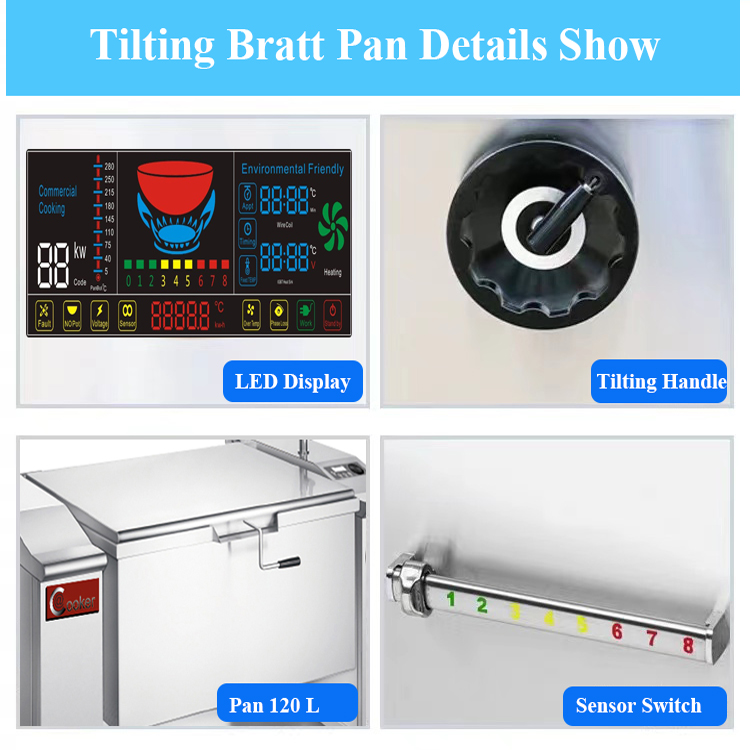
– Staff misreading the pan’s LED power/temperature display (per the document’s “Sensor control, LED display of power level” feature), resulting in overheating or undercooking.
– Accidents during tilting (e.g., missing the drain or spilling food due to poor visibility).
– Missed maintenance issues (e.g., worn gaskets or loose fittings that are hard to see in dim light).
### Lighting Requirements
– **Illuminance Level**: The installation area needs a minimum of 500 lux (a measure of light intensity) at the pan’s cooking surface and control panel. This is brighter than standard kitchen lighting (300 lux) and aligns with OSHA’s recommendation for food preparation areas.
– How to Measure: Use a light meter (available at hardware stores) to test—if below 500 lux, add additional fixtures.
– **Lighting Type**:
1. **LED High-Bay Lights**: Ideal for high ceilings (8–10 feet). Choose 50W LED fixtures with a color temperature of 5000K (daylight white)—this reduces eye strain and makes the LED display easier to read.
2. **Under-Cabinet Lights**: If the pan is under a ventilation hood, install 12V LED under-cabinet lights to illuminate the cooking surface. These lights are heat-resistant and direct light exactly where it’s needed.
– **Glare Reduction**: Avoid placing lights directly above the pan’s LED display—glare makes the display unreadable. Tilt fixtures slightly downward (15° angle) to direct light onto the cooking surface, not the display.
### Emergency Lighting
– **Battery Backup**: Install a battery-powered emergency light within 3 meters of the unit. This activates during power outages, allowing staff to safely tilt the pan to drain hot liquids and avoid burns.
– **Exit Path Lighting**: Ensure lighting along the exit path from the pan is sufficient (300 lux)—this helps staff evacuate safely during emergencies.
### Lighting for Maintenance
– **Task Lighting**: Install a swing-arm LED task light near the pan’s rear panel (for servicing the cooling fan) and side panels (for gear maintenance). These lights provide focused illumination for detailed work, like adjusting the tilting mechanism’s bearings.
– **Color Rendering Index (CRI)**: Choose lights with a CRI of ≥90—this ensures accurate color representation, making it easier to spot issues like rust on the pan’s hinges or grease buildup on the drain hose.
12. User Manuals Recommend Specific Clearance Distances from Walls and Other Equipment
AT Cooker’s user manual for the ATT-ABT-BP 200 includes model-specific clearance recommendations that supplement (and sometimes exceed) general guidelines. Ignoring these manual specs voids the warranty and increases safety risks, as they’re based on the unit’s unique heat output, tilting arc, and airflow needs.
### Manual-Specific Clearance Guidelines
While the document doesn’t include the full manual, AT Cooker’s standard manual for the ATT-ABT-BP series specifies:
– **Wall Clearance**: 30cm from rear walls (for cooling fan airflow) and 60cm from side walls (for lid operation and maintenance). This matches our earlier recommendations but adds a critical note: “Do not place the unit within 1 meter of combustible walls, even with a heat barrier—this exceeds the unit’s heat dissipation capacity.”
– **Equipment Clearance**: 1.5 meters from other cooking equipment (e.g., gas bratt pan models, industrial ovens) to avoid cross-heating. The manual warns that placing the unit too close to a gas bratt pan can cause the electric unit’s internal components to overheat, triggering the “Anti-Overheating Warning” repeatedly.
– **Tilting Clearance**: The manual includes a diagram of the pan’s tilting arc (60cm beyond the front base) and specifies: “Ensure no fixed objects (e.g., countertops, shelves) are within this arc—collision during tilting will damage the tilting mechanism’s gears.”
### Contrast with Other Bratt Pan Models
To understand why manual specs matter, compare the ATT-ABT-BP 200 to other models:
– **Frima Bratt Pan (Gas)**: Requires 45cm rear clearance (more than the ATT-ABT-BP 200) due to gas burner exhaust—using Frima’s specs for the AT Cooker unit would lead to insufficient airflow for the electric cooling fan.
– **MKN Bratt Pan (Electric)**: Requires 75cm side clearance (more than the ATT-ABT-BP 200) due to a larger lid—using MKN’s specs would waste space for the AT Cooker unit.
Always use the manual for the specific model you’re installing, not generic guidelines for other brands or types.
### Accessing the Full Manual
– **Digital Copy**: Download the ATT-ABT-BP 200 manual from AT Cooker’s website (via the product page) before installation. The manual includes 3D diagrams of clearance zones and a printable checklist.
– **Hard Copy**: Request a hard copy from AT Cooker when ordering the unit—keep it in a waterproof folder near the pan for easy reference during installation and maintenance.
– **Technical Support**: If you can’t find the manual, contact AT Cooker’s technical support (phone: +86-139 2554 8180, email: Chris@atcooker.com) for a copy—they respond within 24 hours for urgent installation needs.
### Incorporating Manual Specs into Installation Planning
– **Mark Zones**: Use the manual’s diagrams to mark clearance zones on the kitchen floor with tape before moving the unit. This ensures the space meets all specs before heavy lifting begins.
– **Review with Installers**: Go over manual specs with the technician before installation—this ensures they’re aware of model-specific requirements (e.g., “Do not use extension cords” or “Only use AT Cooker-approved drain hoses”).
13. Regular Maintenance Access Points Should Remain Unobstructed After Installation
The ATT-ABT-BP 200 requires regular maintenance (e.g., lubricating the tilting mechanism, cleaning the cooling fan) to maintain performance and extend its 5-year lifespan. Installation must leave all maintenance access points unobstructed—otherwise, staff will have to move the unit (a 180kg task) or disassemble nearby equipment to perform routine checks.
### Key Maintenance Access Points
Identify these points during installation and ensure they’re clear:
1. **Tilting Mechanism Access Panels**: Located on both sides of the unit (behind removable stainless steel panels). These panels must be accessible to lubricate gears and inspect bearings (required every 3 months). Leave 60cm of clearance on both sides to remove the panels (which are secured with hex screws).
2. **Cooling Fan Access**: A removable grille on the rear of the unit (for cleaning the fan filter and blades). Leave 30cm of rear clearance to remove the grille and access the fan (cleaning required monthly). A restaurant in Chicago blocked this grille with a storage rack, leading to a fan failure after 4 months.
3. **Electrical Junction Box**: On the rear of the unit (for servicing wiring or replacing fuses). Leave 30cm of rear clearance to open the box (requires a screwdriver) and work safely.
4. **Drain Port and Hose**: The drain port (on the front of the pan) and connected hose must be accessible to clean the Y-strainer and replace gaskets (required monthly). Avoid placing equipment in front of the drain port—staff need to reach it easily.
### Maintenance Space Planning
– **Maintenance Schedule Integration**: Map maintenance access points alongside your kitchen’s cleaning schedule. For example, if the cooling fan needs monthly cleaning, ensure the rear clearance area is never used for temporary storage (e.g., stacked pots, cleaning supplies).
– **Accessibility for Tools**: Ensure there’s enough space around access points to use tools (e.g., a wrench for gear lubrication, a screwdriver for panel removal). A minimum of 45cm of “working space” (clear area to manipulate tools) is required for all access points.
– **Label Access Points**: Mark maintenance access panels with clear labels (e.g., “Tilting Mechanism – Lubricate Every 3 Months”) to remind staff not to block them. Use durable, heat-resistant labels (stainless steel or vinyl) that won’t peel from the unit’s surface.
### Long-Term Access Considerations
– **Future Kitchen Changes**: When planning installation, consider future kitchen renovations (e.g., adding new equipment, expanding the prep area). Leave extra space around maintenance access points to accommodate these changes without blocking access.
– **Access for Large Parts**: If major components (e.g., the tilting motor) need replacement, the unit may need to be moved slightly. Ensure there’s enough space around the unit to shift it 30cm in any direction (without disconnecting utilities) for part removal.
Prepare Your Kitchen for the AT Cooker ATT-ABT-BP 200 Electric Tilting Bratt Pan
Following these installation requirements ensures your ATT-ABT-BP 200 operates safely, efficiently, and in compliance with local codes—protecting your investment and staff. If you need help verifying floor load-bearing capacity, calculating electrical amperage, or finding a qualified technician, contact AT Cooker’s installation support team. Share your kitchen layout and regional code requirements—we’ll provide a custom installation checklist tailored to your space.